Setting up the PEPS II and DM air system
This procedure details how to set up the air supply for the self-leveling floating table system (PEPS II) and the MEMS DMs. The procedure was documented in the LCO clean room, but these steps should be mimicked when installing MagAO-X on the telescope.
Estimated time to complete if MagAO-X is not on legs: 1.0 hr Estimated time to complete if just setting up air: 0.5 hr
If MagAO-X has yet to be installed on the Legs
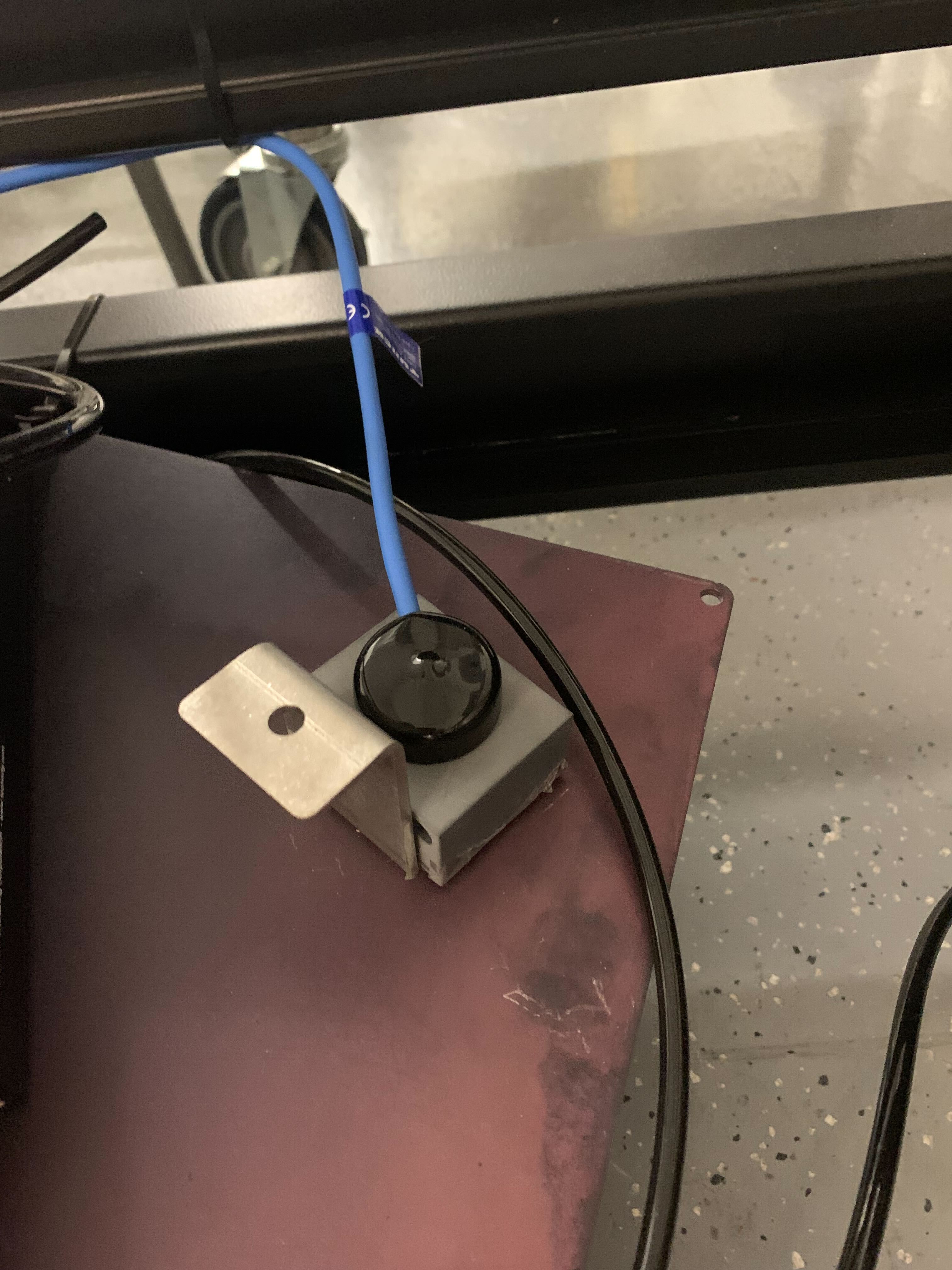
This is a geophone. Dust cover may or may not be attached.
Locate all geophones in basket (leave in basket, but ensure no tangles).
Locate table air power plug and remove from basket if needed.
Remove “air in” hose from basket if needed.
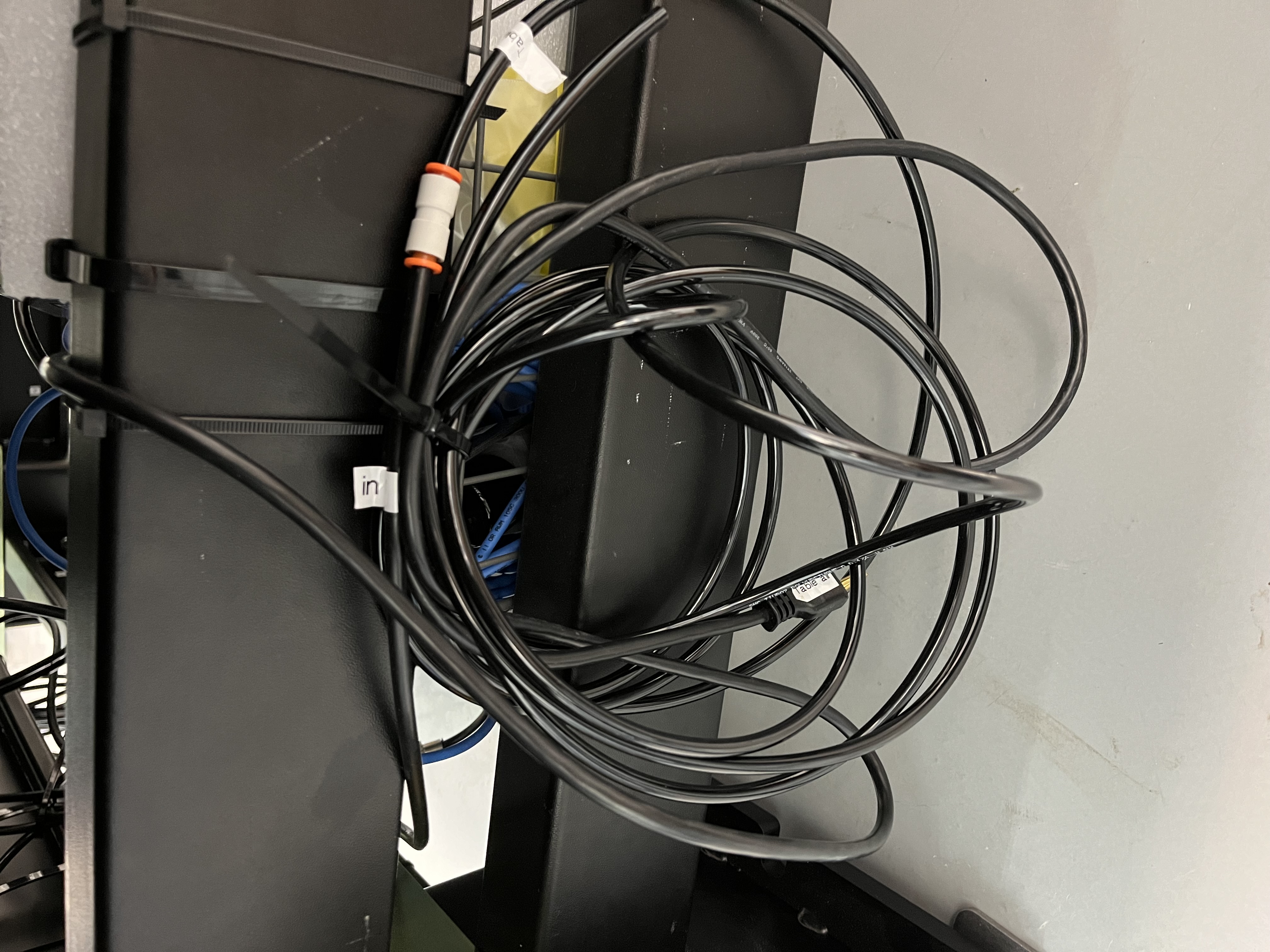
Power plug and “air in” hose may be hanging on side of legs.
Center each rubber platter onto its pedestal and dry dust the rubber to remove any debris.
Carefully slide the legs under MagAO-X when it is being craned.
Center legs under the instrument in both directions (length/width)
Slowly lower the instrument onto the platters.
When MagAO-X is installed onto the legs
Wheel the instrument into the clean tent or onto the telescope platform.
Take each geophone and attach them to their labeled corners (a –> A, etc.). Take care not to drop as they might separate from the steel plate!
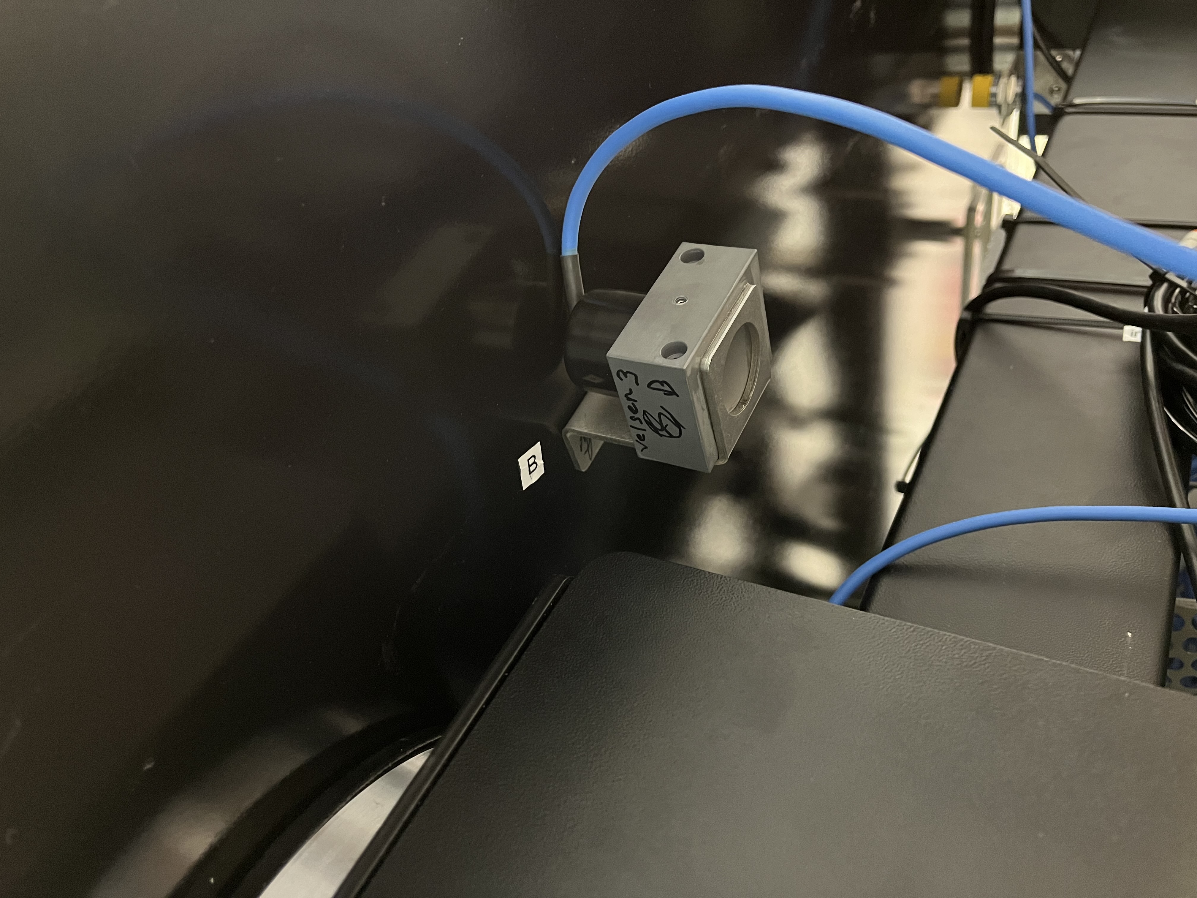
Mount the geophones in the illustrated orientation.
Use short length 1/4-20 bolts because longer ones will bottom out before clamping the geophone flange to the bottom of the frame.
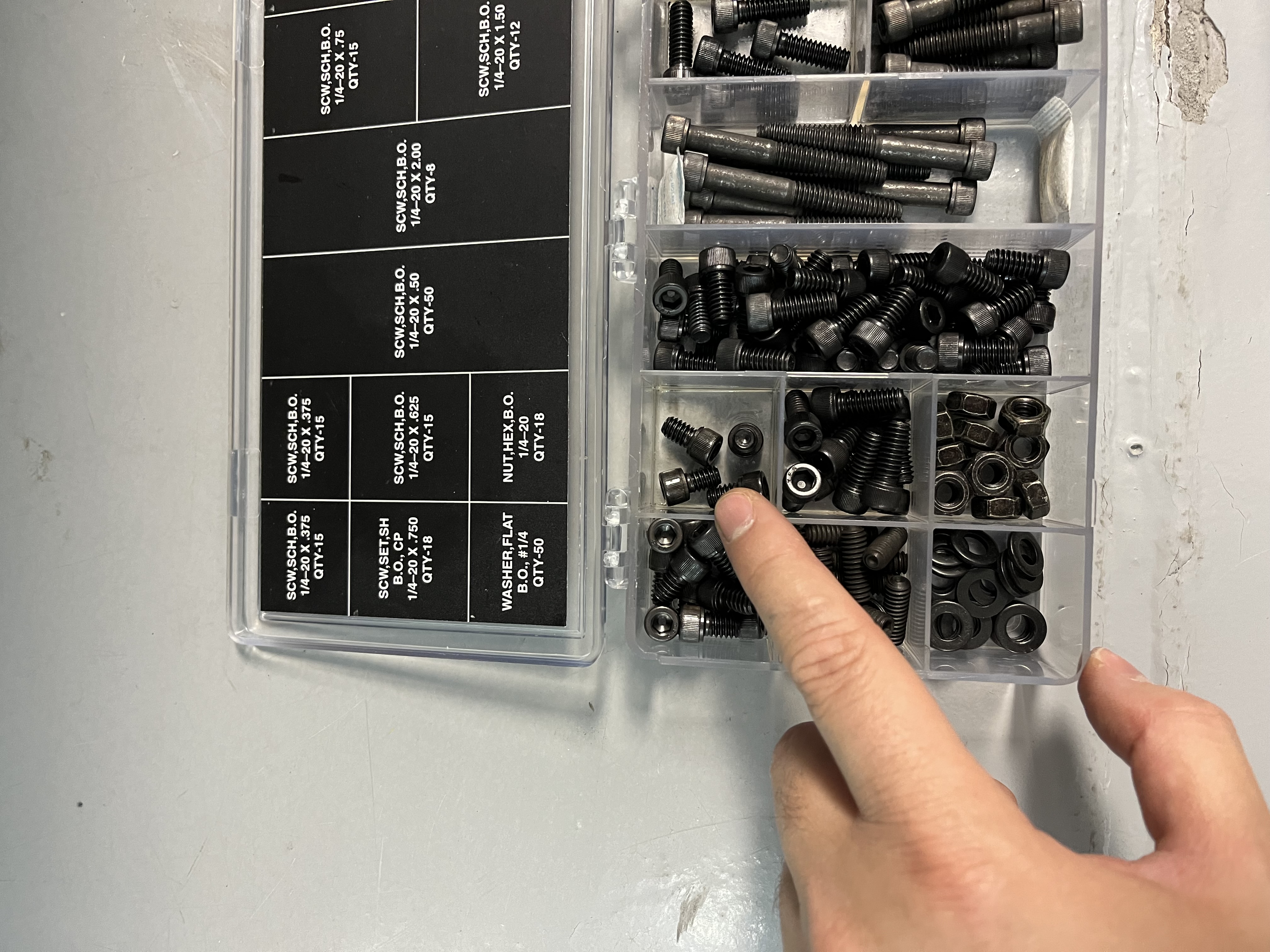
1/4-20 bolt size used in 2024Ab
After geophones are mounted, ensure rocker switch on the PEPS II controller is set to OFF (“O” symbol).
Setting up the air system for PEPS II
[TODO add changes when doing at the telescope]
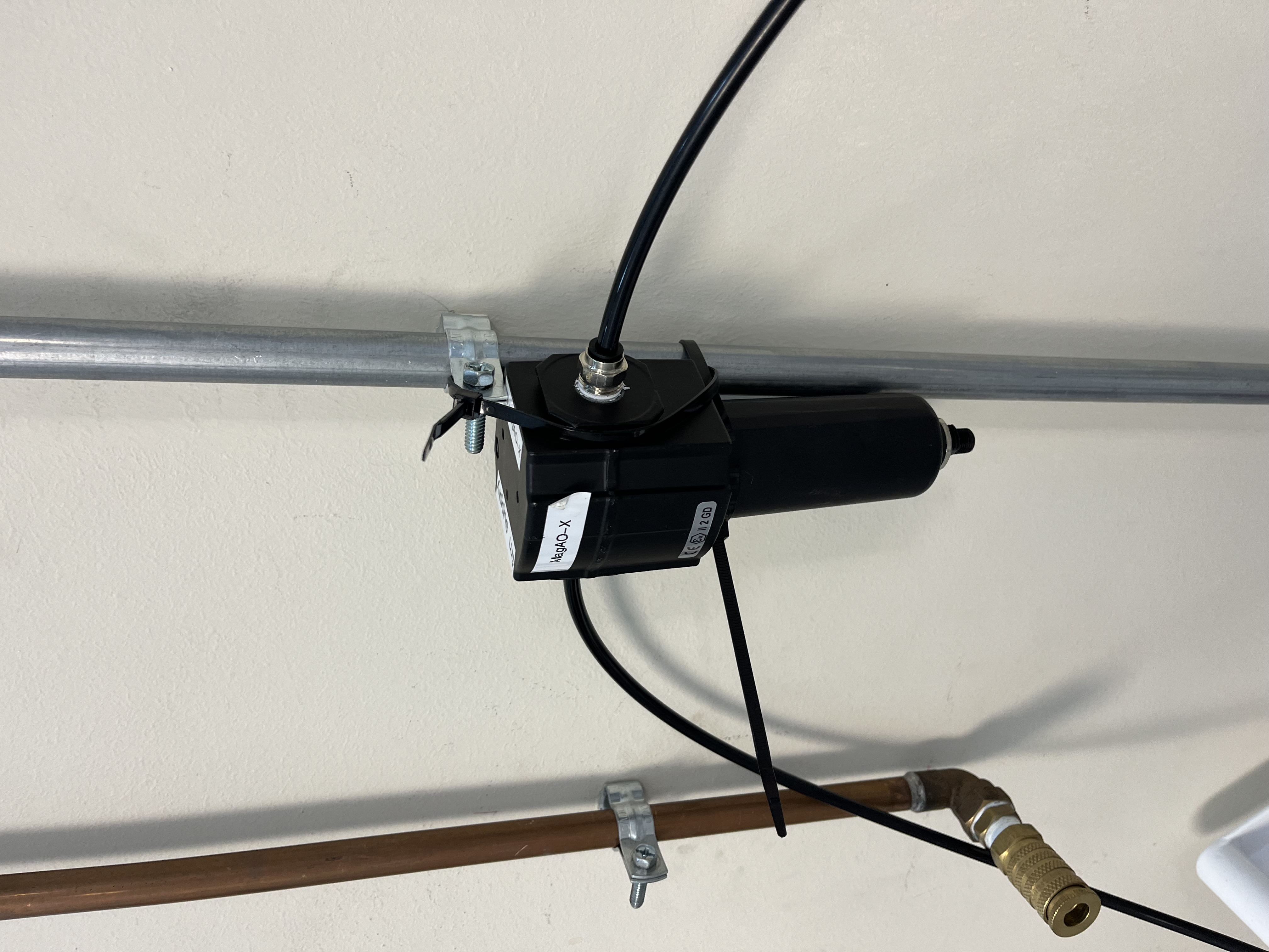
The air drier and filter for the main line connection.
Step 0: Check filter media in the air receiver driers for the legs (black plastic unit, see above) and for the DMs (5 inline white plastic units) for dirt and contamination. Replace if needed.
Step 1: Mount air receiver drier to the wall-mounted metal tubes on the wall behind the clean tent (opposite of entrance) using zip ties, see above.
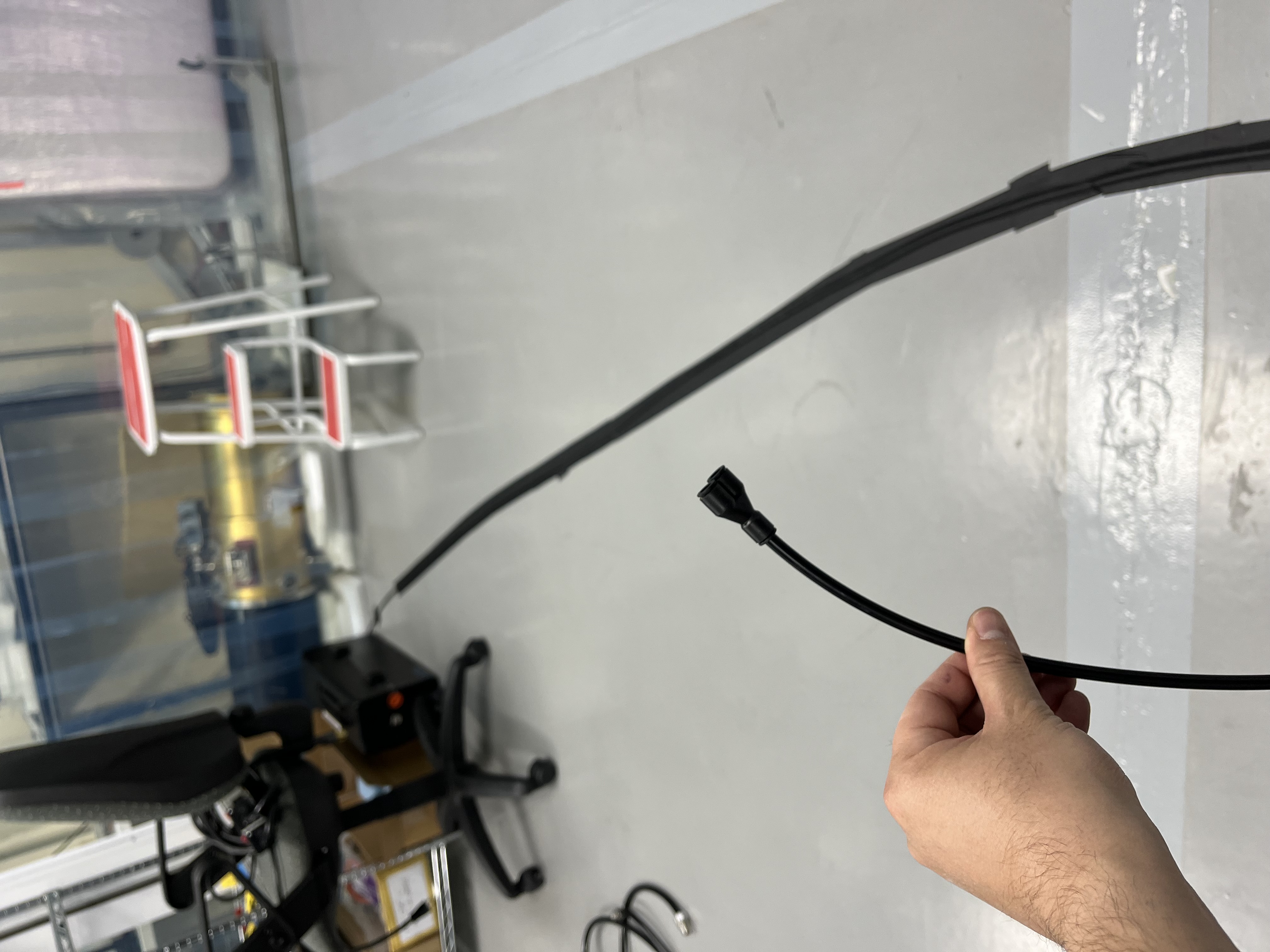
Step 2: Take the long part of the plastic air tubing and lead to the instrument. Tape down the tubing onto the floor to prevent tripping. Locate the y-fitting at the end of the tubing.
Step 3: Connect any one side of the y-fitting to the tubing connected to the air flow regulator. This portion of the air supply will go to the DM chambers for humidity control.
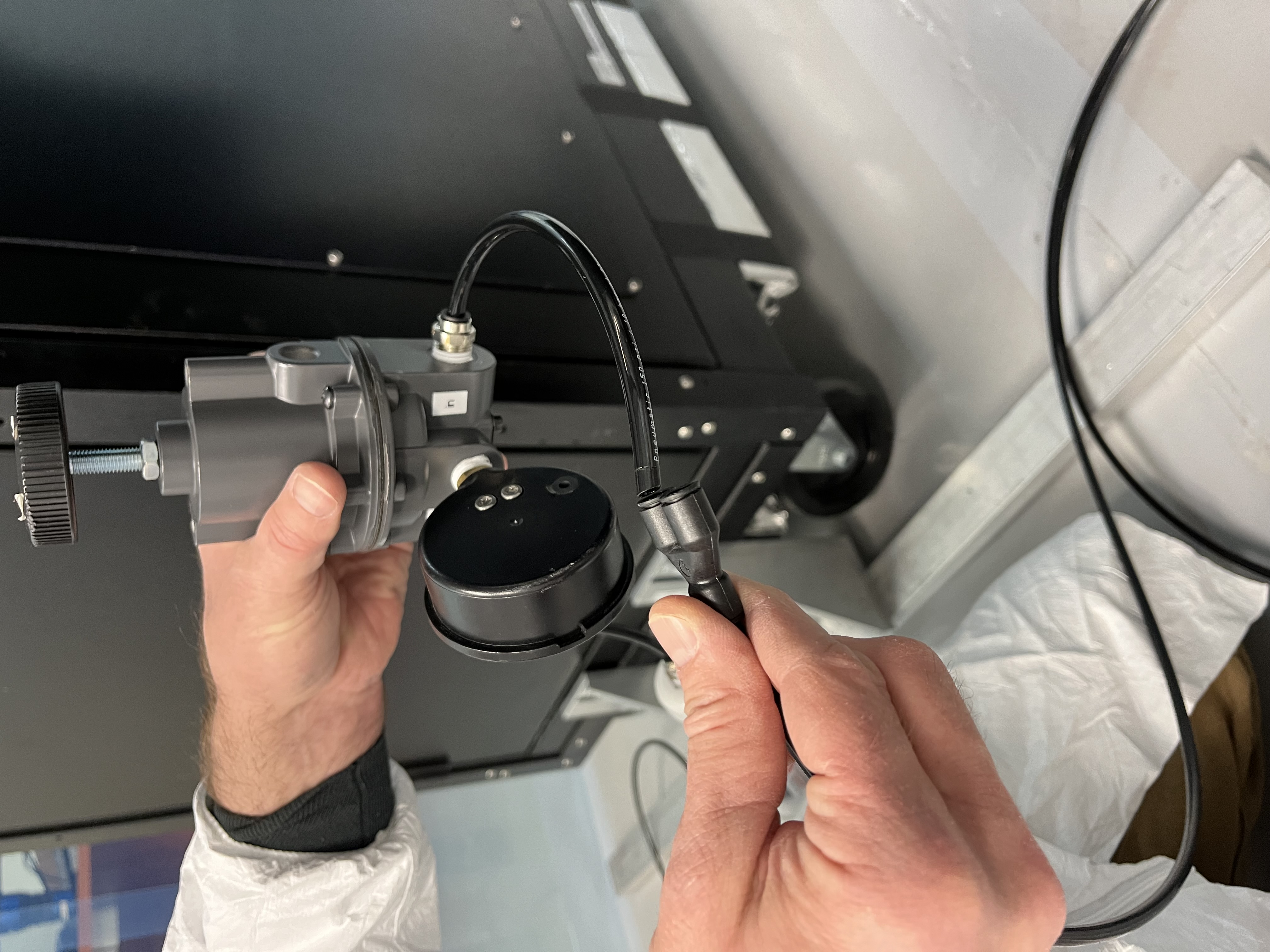
Inlet side of the regulator tubing goes into the any port of the y-fitting. Press fit, gently tug to test connection.
Step 4: Connect the other port of the y-fitting to the legs “air in” tubing. Run the exhaust line outside the clean tent.
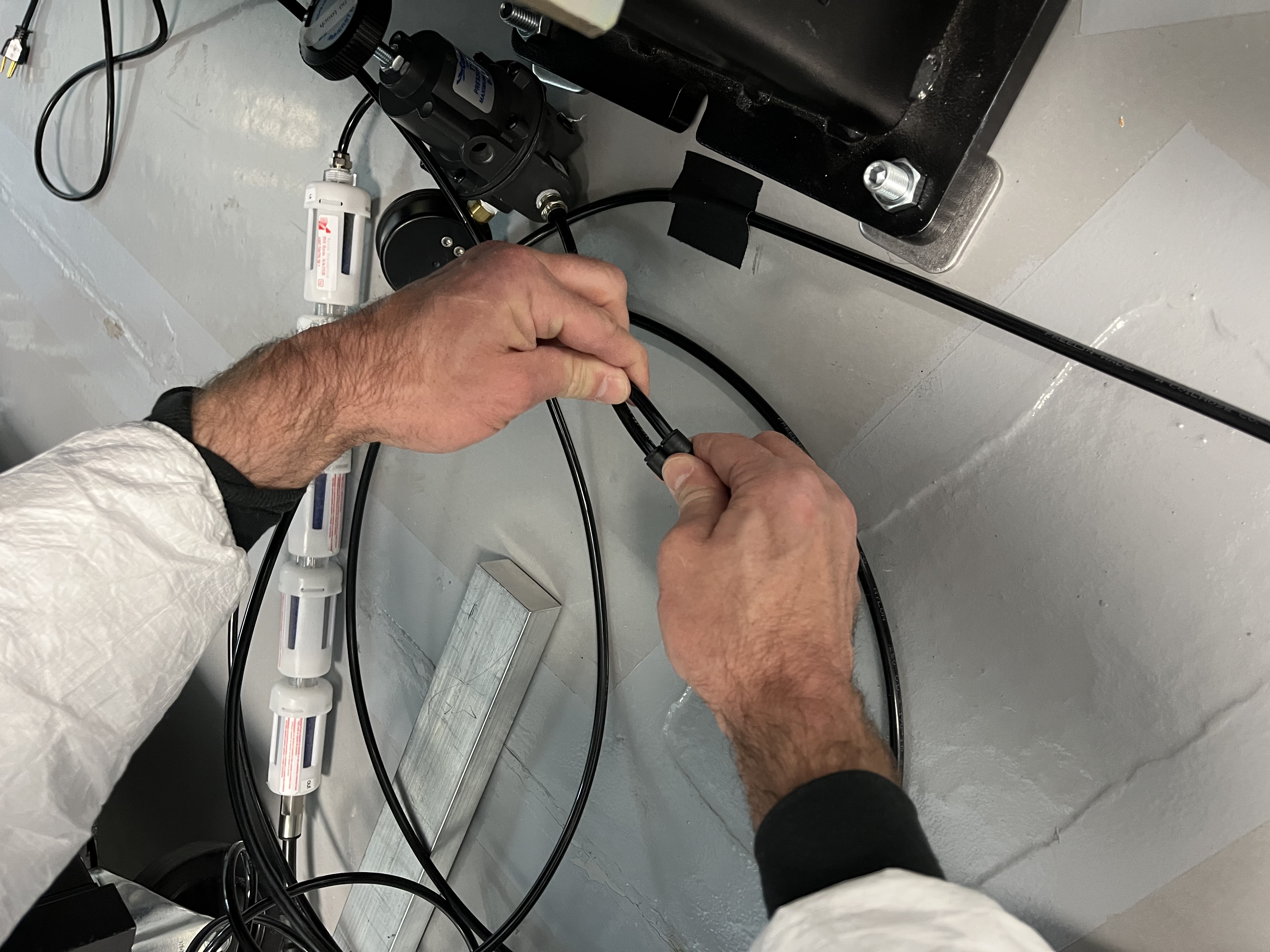
Air-in tubing from the legs goes into the other port of the y-fitting. Press fit, gently tug to test connection.
NOTE: The plastic air tube fittings work like a Chinese finger trap toy. To remove, push the tube in further and hold while using your finger to push down on the rubber collar of the fitting. While holding the collar down, gently pull the tubing out of the fitting.
Step 5: Go back to the back wall of the clean room and take the brass pipe fitting and connect the plastic air tubing from the inlet side of the now wall-mounted black receiver drier. Press the other end of the brass fitting into the brass coupler at the copper air supply line.
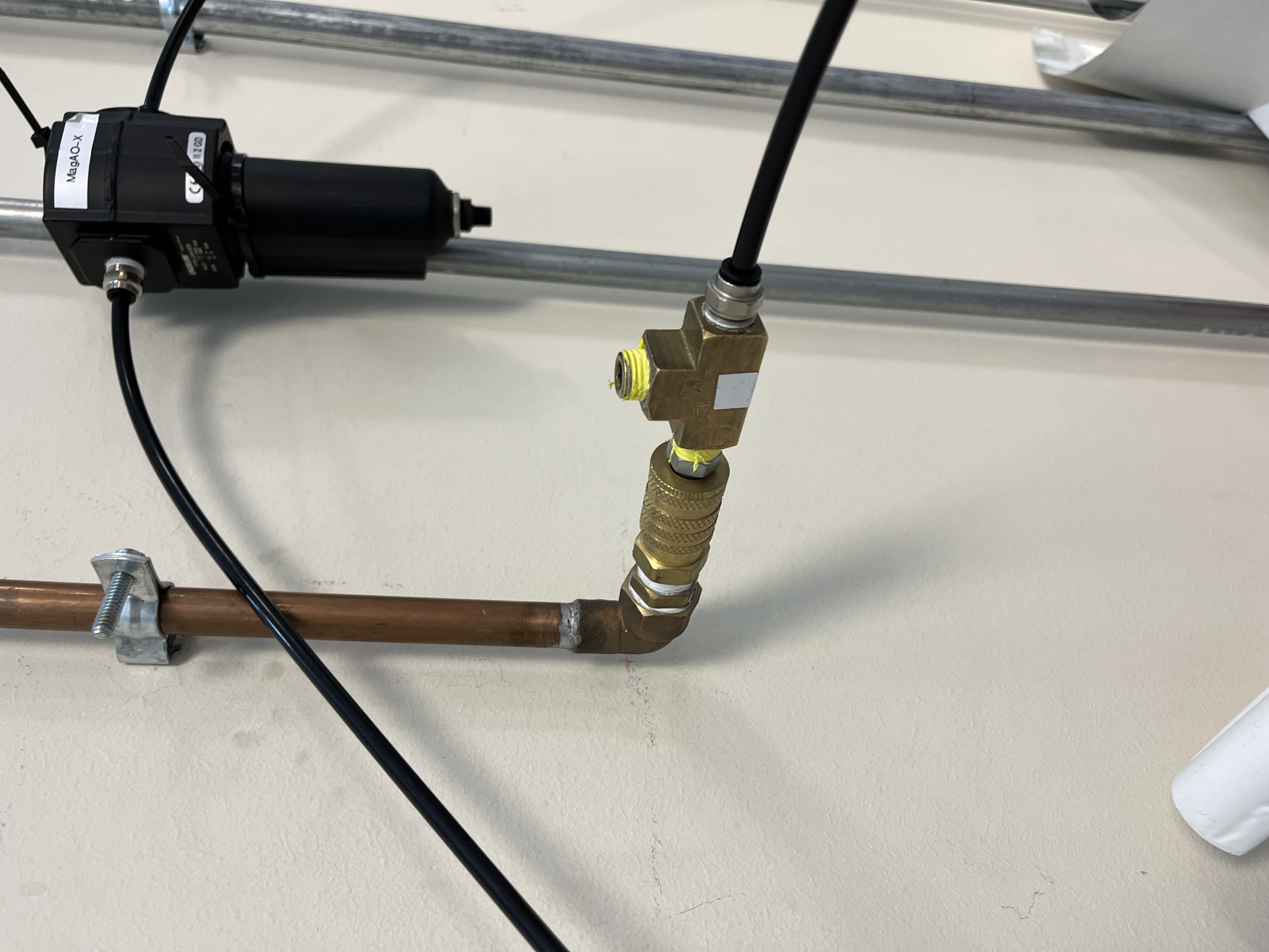
The brass fitting is a straight-through piece, so which side the tube goes into doesn’t matter. Press hard until it clicks and there are no audible leaks.
Step 6: Go back to the legs and plug in the table air power cord. Flip the rocker switch on the PEPS II controller to turn it on.
Step 7: Watch it float and self-calibrate. LED flashes yellow, then solid green after about 2 minutes. Done!
Setting up the dry air for the MEMS DMs
Step 0: Continuing from above, let the air escape freely out of the DM supply side of the air system to purge any debris that may have accumulated within the line while in storage. Wipe the very end of the plastic tubing with isopropyl alcohol to clean it, since this part goes into the instrument.
Step 1: After purging the line, adjust the valve on the regulator to the correct air flow rate. J. Males or K. Van Gorkom can help with this, if they are available.
Step 2: Connect to the DM air feed and monitor humidity levels.