Installing MagAO-X on the Telescope
This procedure describes how to install the MagAO-X instrument on the Magellan Clay Telescope.
Estimated Time to Complete: 5 hours
This document can be downloaded as a PDF: Installing MagAO-X on the Telescope
Advanced Preparations
At least 1 week before the removal date, communicate with the LCO staff to arrange for the following:
Flatbed truck
crane scale (> 2000 lbs)
come-along
4 ratchet straps
Clay jib crane at 3 hairs speed
N2 bottle with regulator and quick-disconnect fitting on the platform
Initial Conditions
Instrument in LCO cleanroom on legs
Preparations
If operating, shut down MagAO-X.
Make sure to leave stages/wheels in positions that are safe for transportation
See complete procedure in the telescope removal procedure
Prepare Legs for Move
Turn off table legs (table air power off, PEPS II rocker switch off) and remove air connection from wall
Lie under table and remove all three (#1,2,& 3) geophones from bottom of table
Place coiled up geophones and cables into basket
Unplug PEPS II power from side of rack
Remove the taped down exhaust line from the clean room floor
Remove all cables
See detailed procedure for removing 2K DM cables
Electronics Rack
Ensure that roll-out shelves are restrained
If not installed, install side panels
Close and lock doors
Tape keys down
Instrument
remove polarimeter
install window cover
Remove eyepiece
Turn off blower, and remove hose
Tape over any exposed holes (from cables, etc)
Secure any loose cables
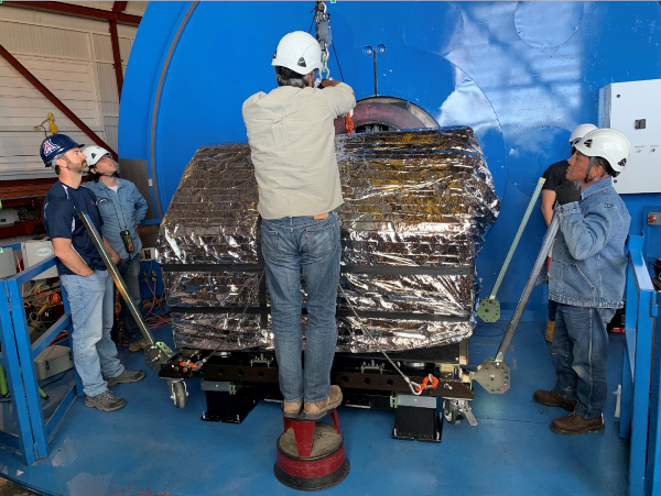
Shrink wrap the instrument
Install solar blanked over shrink wrap
Cart and Rigging
Verify all cart hardware is in-hand
Verify two wire harnesses are in hand
Partially assemble cart, leaving one long side off
Store cart out of the way so table can roll into unpacking area
Dome
The NASE platform shoud be clear and ready for MagAO-X installation
The dome jib crane should be set to “3 hairs” speed
XKID
If XKID is pre-cooling on the platform:
move the electronics to the dome floor
move the dewar to the corner of the platform
ensure cables are routed to minimize interference
Rig Onto Cart
Lower table legs onto the casters by turning the 16 leveling bolts, and remove the 12 metal pads
Roll the instrument out of the cleanroom
NOTE: At least 4 people required, 2 to push, 2 to hold the cleanroom sides open. Additional people are recommended to help guide.
CAUTION: only push on the legs, not the table itself
Continue rolling the instrument through the garage door into the unpacking area
Move the cart, currently with 3 sides, around the legs
CAUTION: be careful to not bump the legs with the cart
Attach the 4th side of the cart
Ensure that the 8 large bolts on the cart are snug but not tight
Attach the lifting wire-harness to each side of the cart. The hooks should point outward.
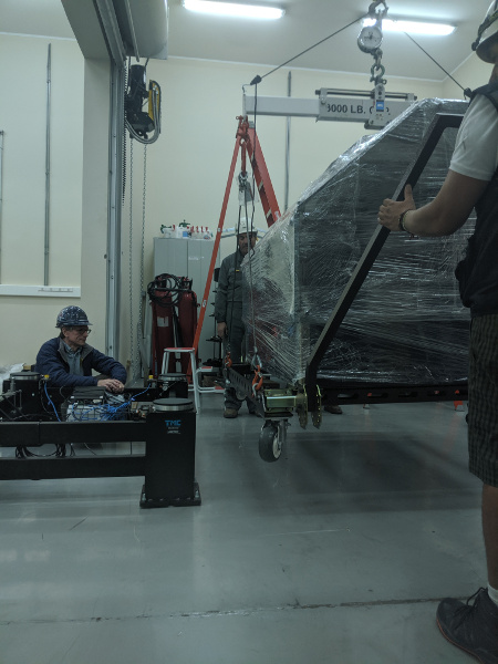
Attach the load spreader with straight extensions to the crane, using a crane scale (note this must be the heavy scale (>2000lbs))
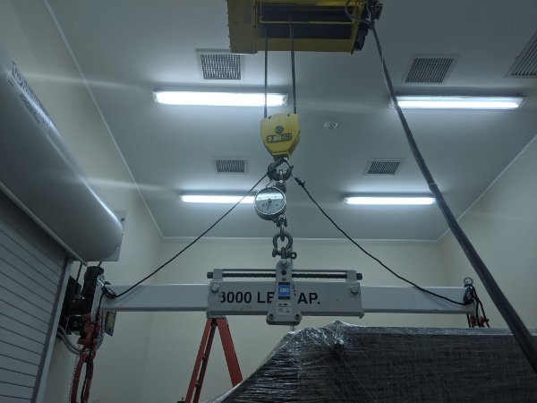
The load spreader attached to the crane for lifting the cart
Place the load spreader in the center position (the cart is symmetric)
Lift the load spreader, and position it over the instrument
Being careful to not bump the instrument, lower the load spreader and attach the lifting harness D rings. Use 4x shackles to extend the length to reach the cart on the floor.
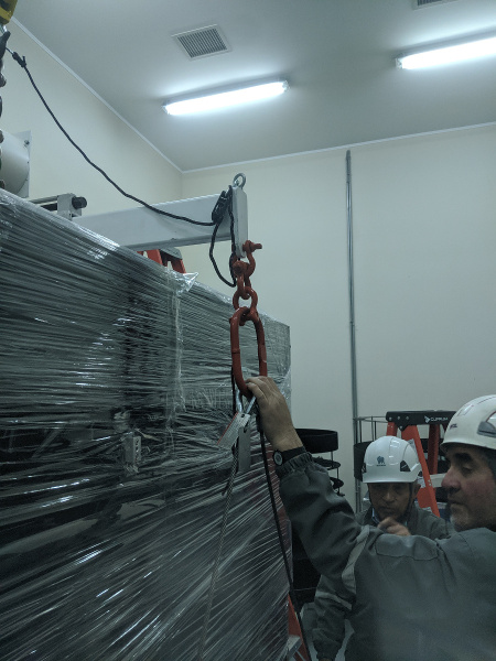
Lifting harnesses attached with shackle extensions
Position a person to hold each of the cart handles
CAUTION: Do not allow the cart to bump the legs or the table uncontrolled
Slowly lift the cart (320 lbs) until it is touching the bottom of the table.
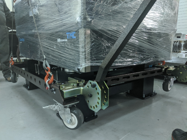
The cart being lifted to the bottom of the table. Note the direction of the hooks.
Install the 4 outboard bolts. Loosen bolts on the cart as needed.
Once the cart is bolted to the table bottom, while 320 lbs is still on the crane, tighten all cart bolts. Do not over-tighten, make 1/4 turn after the washers are no longer free. This is to avoid excessive stress on the table.
Reposition the load spreader center to the instrument + cart position marked on it.
- CAUTION: be sure that the load spreader does not hit the cart when
being repositioned.
Install the triangle stabilizing ropes between the crane hook and the lifting fixture IAW the below figure. Tighten, but do not cause them to pick the load.
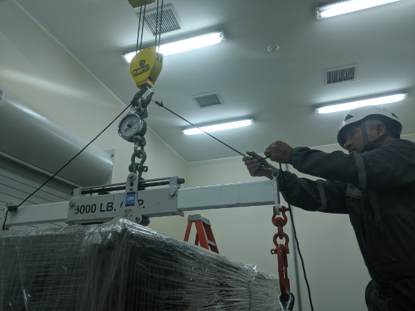
The triangle stabilizing ropes should be tight, but not become the lifting point for the load.
Ensure that there is room to move the legs out from under the table, opening the garage door into the cleanroom if necessary.
Position a person at each of the cart handles to stabilize it during the lift.
Position two people to remove the legs from under the table
Begin SLOWLY lifting the table off the legs. Once table is fully supported by the crane, the scale will read around 2000 lbs (as of March 2024).
Go up 0.5inch then stop and inspect the platters. Use a long flathead screwdriver to very gently pry any stuck platters off bottom of table.
Move the legs out from under the table.
The cart and instrument ready to be set down on the wheels, with legs out of the way.
Set the cart down on its wheels.
Re-check the cart bolts. Tighten any that are loose to 1/4 turn past when the washers stop moving.
Transport MagAO-X To Clay
Move MagAO-X onto the lift gate (using plates over the gap)
MagAO-X moved onto the pentalift. Note the metal plates across the gap.
Raise the lift-gate to the height of the flatbed truck
Pentalift raised to truck height.
Place the plates across the gap.
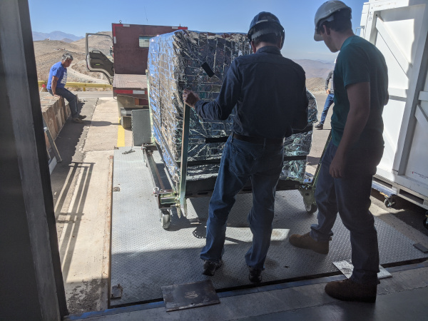
Move MagAO-X onto the truck using the come-along
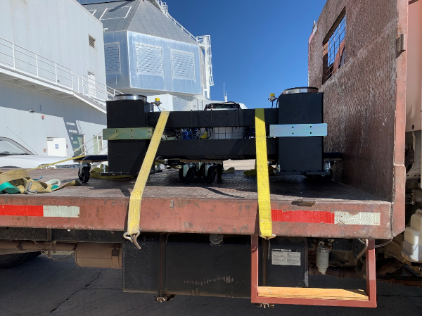
Secure the instrument by strapping the cart down at 4 points as illustrated in the below figure.
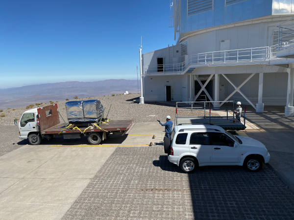
MagAO-X will be strapped to the Isuzu flatbed.
Slowly drive the truck to the summit.
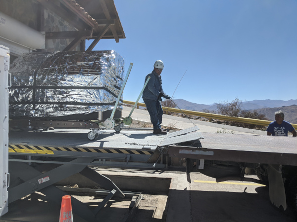
Ensure that the lift gate at the summit has been adjusted for slow smooth operation as is done for the asm
Back the flatbed truck up to the lift gate.
MagAO-X will be unloaded at the telescope using the lift gate, adjusted for slow operation as it is for the ASM.
Next, using the come-along, carefully move MagAO-X onto the lift gate.
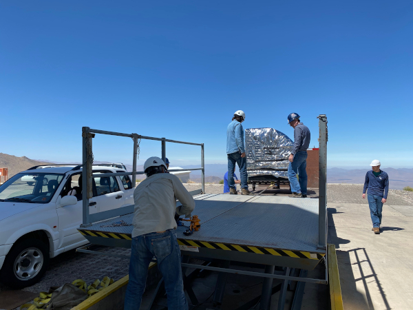
Use the come-along to move MagAO-X on the gate
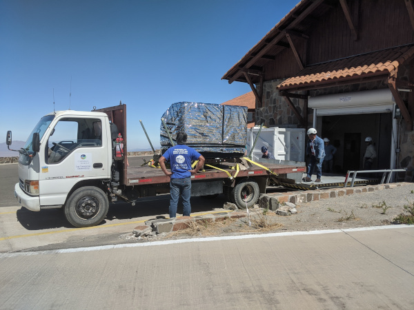
Very slowly so as to minimize vibrations, move MagAO-X to the elevator, or place it in the Aux until ready to move to the elvator.
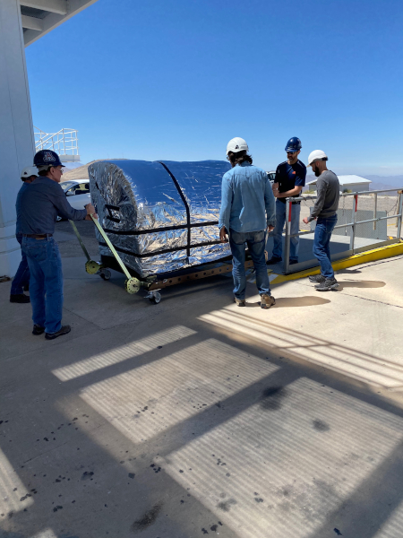
Slowly and carefully move MagAO-X to the telescop or Aux.
Moving the Legs to the Summit
Return to the cleanroom with the flatbed.
Placed on 2 dollies as in the below image.
Legs on 2 dollies placed in the middle of the table under each lower long tie bar (away from basket).
Move the legs to the flatbed and strap them down.
Legs strapped to the truck.
Slowly drive the truck to the summit.
Ensure that the lift gate at the summit has been adjusted for slow smooth operation downwards (slow air release) as is done for the ASM
Back the flatbed truck up to the lift gate.
Next carefully roll legs onto the lift gate.
Remove dollies from legs before going into elevator.
Bring the load spreader and rigging up with the legs.
Install MagAO-X On The Platform
Ensure the dome jib crane is set to “3 hairs” speed
Position the telescope so that the elevator has access to the NASE platform
Put MagAO-X on the NASE platform
Put the legs on the elevator and raise it the platform
Set the alignment pin system on the legs for receiving the instrument, and ensure that the platters are centered on the legs.
Attach the load spreader using the wire harnesses as above
Install the triangle stabilizing ropes
Position a person at each corner of the instrument to stabilize it
Lift the instrument with cart until it will clear the legs
Move the legs under the instrument.
Ensure that the table pads are centered
While keeping the instrument level, very slowly lower it into position using the alignment pins.
If one side touches first platters will move and repeat last few steps until platters are centered and pins are centered
Once on the legs, unload the crane to the cart weight of 320 lbs and re-position the load spreader for the cart
Adjusting the load spreader for the cart.
With the crane supporting the cart weight, remove the 4 bolts attaching the cart to the table
Lower the cart to the floor, and detach from the crane.
Stow the crane and handling gear
Remove the long side of the cart on the telescope side (4 bolts), and wheel the remaining pieces out from under table. Reassemble the cart and remove to the Aux. Bldg.
Conduct the daytime alignment procedure per alignment plan
See detailed alignment procedure Aligning MagAO-X to the Telescope
Transport Electronics
remove the earthquake bar
Use the lift gate to move the electronics rack onto a truck (either the flatbed or a pickup)
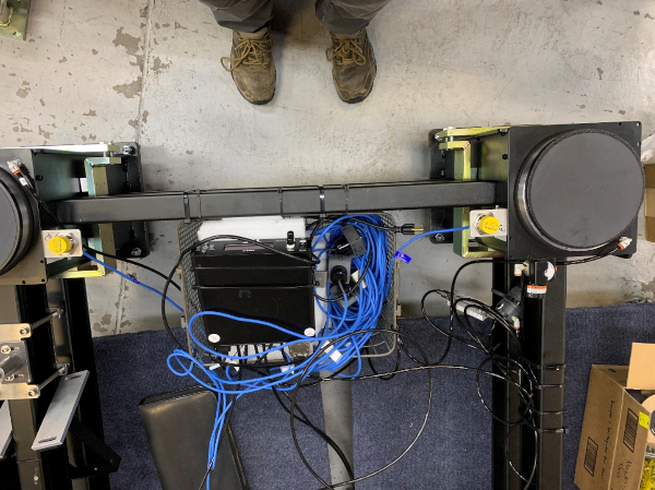
place foam between the rack side and the truck to protect cable connectors
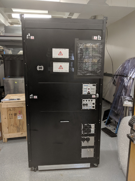
The electronics rack has many delicate connectors on the side.
strap the rack securely to the truck using the D-rings (do not compresss the foam on the top with straps)
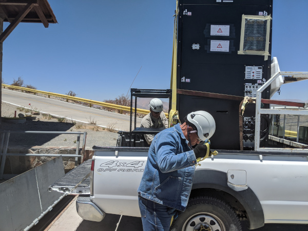
The rack on a truck for transport.
drive the truck to the summit
unload the rack using the lift gate, and move to the platform on the elevator
Install Electronics and Cable
- If needed, unplug from UPS power outlet to free up sockets:
MIKE CCD controller
telescope’s ADC (after retracting)
others’ fiber media converter
Place the rack in position next to the instrument. Leave enough room behind it so that the door can open.
Install the earthquake roll bar
lock the wheels
Check that the rack is stable and will not roll
Install all cables but the 2K DM cables
Power on the UPS located in the electronics rack
Install AOC in Control Room
Move the AOC, monitors and stand to the Clay control room
Connect AOC to the telescope 200 network, and to the “VisAO” port for the internal 192 network.
Connect the “VisAO” cable behind the MagAO rack in the equipment room directly to the media converter for VisAO.
On the platform connect the instrument lan to the VisAO fiber with a media converter
Power on the AOC
Conduct function checks of everything but the 2K DM
Cable the 2K
Cable the 2K DM following procedure
See MagAO-X PSR Document 2.2 Deformable Mirrors
Check actuator functionality, following this notebook on the RTC